
Understanding Pipe Fitting Friction Loss
Definition of Friction Loss – Explaining what friction loss is in piping systems
Friction loss in piping systems is often the silent thief of efficiency, quietly draining energy and increasing operational costs—yet, it’s a concept surprisingly easy to grasp once understood. At its core, friction loss refers to the resistance that fluid encounters as it journeys through pipes, fittings, and valves. Think of it like a boat battling against a gentle current; the more obstacles, the greater the resistance.
When navigating the complex world of pipe fitting friction loss, having a reliable pipe fitting friction loss table is invaluable. Such tables serve as a quick reference, translating the labyrinth of pipe sizes, fittings, and flow rates into clear, actionable data. They illuminate how various fittings—elbows, tees, reducers—contribute to the overall friction loss, ensuring engineers and technicians can optimize their systems with confidence.
For those passionate about precision, understanding how to interpret this table is essential. It provides a nuanced picture of how each component influences flow, enabling smarter choices and more efficient piping designs. After all, in the realm of fluid dynamics, every fraction of pressure saved is a victory for operational excellence.
Importance in Plumbing and HVAC – Why accurate friction loss calculations are essential
In the intricate dance of plumbing and HVAC systems, the silent influence of friction loss can make or break operational harmony. Imagine a grand river navigating through a labyrinth of twists, turns, and obstacles—each element adding resistance and subtly draining its energy. This is precisely what occurs within piping systems, where every bend, valve, and fitting contributes to the overall pipe fitting friction loss. Understanding this phenomenon is paramount, especially when striving for optimal efficiency in South African installations that demand resilience and precision.
The importance of a comprehensive pipe fitting friction loss table cannot be overstated. It transforms complex variables—such as pipe diameter, fitting type, and flow rate—into a consolidated map of resistance. This enables engineers and technicians to foresee how each component influences the system’s pressure and flow, avoiding costly surprises down the line. Whether designing a new HVAC network or upgrading an existing plumbing system, accurate friction loss calculations ensure that every drop of water or cubic meter of air travels with minimal resistance, conserving energy and reducing operational costs.
Key Factors Influencing Friction Loss – Pipe material, diameter, flow rate, and fitting types
Understanding the key factors that influence pipe fitting friction loss is essential for designing efficient plumbing and HVAC systems. These factors determine how much resistance the fluid encounters as it moves through the piping network, directly impacting energy consumption and system longevity. Among the most significant are pipe material, diameter, flow rate, and fitting types—each playing a pivotal role in the overall friction loss.
Pipe material affects the internal surface roughness, which in turn influences how much friction is generated. For example, smooth materials like PVC tend to produce less resistance compared to rougher metals. Diameter is equally critical; larger pipes generally offer lower friction loss because they allow for a greater flow area. Conversely, higher flow rates increase turbulence, elevating friction loss levels.
Fitting types—such as elbows, tees, and valves—also contribute substantially to resistance. To simplify the complex interactions between these variables, a well-structured pipe fitting friction loss table becomes invaluable. This table consolidates data on various pipe sizes, materials, and fitting types, providing a quick reference that helps engineers predict pressure drops accurately. With this resource, professionals can optimize system performance and prevent costly inefficiencies.
Components of a Pipe Fitting Friction Loss Table
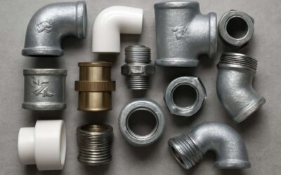
Types of Pipe Fittings Covered – Elbows, tees, reducers, couplings, and more
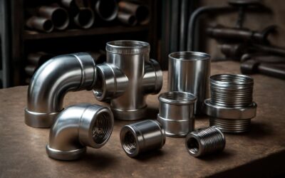
In the intricate dance of fluid dynamics within piping systems, understanding the components of a pipe fitting friction loss table is paramount. These tables serve as the silent architects of efficiency, capturing the subtle yet significant impact of diverse fittings on flow resistance. The components typically encompass a range of fittings—elbows, tees, reducers, couplings, and valves—each contributing uniquely to the overall friction loss. Recognizing how each element influences pressure drop allows engineers and plumbers to optimize system design with precision and confidence.
Within a comprehensive pipe fitting friction loss table, you’ll find detailed friction coefficients assigned to every fitting type. These coefficients translate into valuable data that streamline calculations, ensuring smooth operation and energy conservation. For instance, elbows and tees often account for a substantial portion of the total pressure loss, especially in systems where fluid velocities are high. By meticulously consulting these tables, professionals can anticipate and mitigate flow disruptions, leading to safer, more reliable piping networks in South Africa’s diverse industrial landscapes.
Data Included in the Table – Friction loss coefficients, flow rate ranges, and fitting specifications
At the heart of every efficient piping system lies a hidden but critical tool: the pipe fitting friction loss table. These tables are not mere charts; they are a blueprint for understanding how various fittings influence fluid movement—an intricate puzzle that can make or break system performance. Inside, you’ll uncover detailed friction loss coefficients that serve as the key to precise calculations, especially vital in South Africa’s diverse industrial sectors. These coefficients are more than numbers—they are the silent architects guiding engineers toward optimized flow and energy savings.
Beyond the coefficients, a comprehensive pipe fitting friction loss table includes flow rate ranges tailored for specific fittings. These ranges illuminate how different components behave under varying velocities, ensuring that system designs are neither overbuilt nor underperforming. Additionally, fitting specifications such as dimensions, angles, and material compatibility are meticulously documented, providing essential context for accurate application. This holistic approach helps professionals anticipate pressure drops with confidence, even when navigating complex piping layouts.
To streamline decision-making, many pipe fitting friction loss tables feature a structured layout—sometimes an ordered list—that clearly delineates how each fitting type, from elbows to reducers, impacts flow resistance. Recognizing these subtle but significant factors ensures that every component is accounted for, fostering safer, more reliable piping networks. In the often unpredictable industrial landscapes of South Africa, this detailed data becomes an indispensable tool for maintaining operational excellence and conserving energy at every turn.
Units of Measurement – Common units used in friction loss tables (e.g., ft/100 ft, psi/100 ft)
In the realm of piping wizardry, understanding the units of measurement within a pipe fitting friction loss table is akin to mastering the language of flow itself. These tables often employ common units such as feet per 100 feet (ft/100 ft) or pounds per square inch per 100 feet (psi/100 ft) — each a precise measure of how much pressure is lost as fluid journeys through a labyrinth of fittings and turns.
Such units serve as the compass guiding engineers through complex calculations, ensuring that every bend and reducer contributes to an optimized system performance. The pipe fitting friction loss table transforms abstract data into tangible insights, revealing how subtle variations in pipe diameter, material, and flow velocity influence pressure drops. For professionals navigating South Africa’s diverse industrial landscape, these measurements are invaluable for designing resilient, energy-efficient piping networks.
- Feet per 100 feet (ft/100 ft)
- Pounds per square inch per 100 feet (psi/100 ft)
By translating the nuances of fluid dynamics into these familiar units, the pipe fitting friction loss table becomes an essential tool—unlocking the secrets of seamless, sustainable flow within the intricate tapestry of South Africa’s industries.
How to Read and Use a Pipe Fitting Friction Loss Table
Locating the Correct Fitting – Identifying the fitting type and size
When navigating the labyrinthine world of piping systems, the pipe fitting friction loss table emerges as an indispensable compass. To read one effectively, start by pinpointing the specific fitting type and size—these are the bedrock details that ensure accuracy. It’s akin to choosing the right tailor for a bespoke suit; a mismatch could lead to costly miscalculations. Once you’ve identified the fitting, consult the table’s coefficients, typically expressed in units like ft/100 ft or psi/100 ft, and match them against your flow rate range. This helps you estimate the pressure drop precisely, preventing surprises down the line.
Locating the correct fitting within the table can be a nuanced task, often involving a quick scan of the flow rate columns and fitting categories. Remember, the table isn’t a static document; it’s a living record of the myriad combinations of pipe material, diameter, and fitting type. For instance, elbows and tees have distinct friction loss coefficients that can dramatically influence the overall system performance. A keen eye and a bit of patience will serve you well in translating these data points into practical, real-world solutions.
Interpreting the Data – Understanding coefficients and flow rate impact
Understanding how to read and interpret a pipe fitting friction loss table can be a game-changer in designing efficient piping systems. These tables are more than just collections of numbers; they are cryptic maps revealing the hidden resistance within every bend and joint. The key lies in grasping the significance of coefficients—values that quantify how much each fitting contributes to pressure drop. These coefficients, often expressed in units like ft/100 ft or psi/100 ft, directly influence how your system performs under specific flow conditions.
Flow rate impact is equally critical. As flow increases, the friction loss tends to escalate non-linearly, making it essential to match your system’s flow range with the appropriate data from the table. When navigating a pipe fitting friction loss table, focus on the fitting type—be it an elbow, tee, or reducer—and carefully locate its corresponding coefficient. This meticulous process transforms raw data into reliable predictions of pressure drop, helping prevent costly inefficiencies and system failures.
- Identify the fitting type and size.
- Match the flow rate with the table’s range.
- Use the coefficient to calculate pressure loss accurately.
In the realm of piping design, this nuanced understanding of the pipe fitting friction loss table unlocks precision, ensuring your systems operate smoothly and efficiently—even in the most complex configurations.
Applying the Data to System Design – Calculating total head loss in piping systems
In the shadowed corridors of piping design, the pipe fitting friction loss table stands as a secret map—each number a clue to understanding the labyrinth of resistance that lurks within every bend and joint. To unlock its mysteries, one must first identify the fitting type and size, for these are the keys to deciphering the hidden language of coefficients and flow rates. With a steady hand, locate the corresponding data that matches your system’s flow range, ensuring precision in your calculations.
Applying this data to system design involves a meticulous process—calculating total head loss isn’t merely summing numbers; it’s weaving a tapestry of fluid dynamics that ensures your pipes breathe with efficiency. By translating the coefficients into pressure drops, you unveil the true cost of each fitting’s resistance. This dark art of calculation transforms raw figures into vital insights, empowering engineers to craft piping systems that are both resilient and elegant in their function.
- Identify the fitting type and size within the pipe fitting friction loss table.
- Match your system’s flow rate with the appropriate range in the table.
- Use the coefficient to accurately determine the pressure loss introduced by each fitting.
Factors Affecting Friction Loss in Pipe Fittings
Flow Velocity and Volume – Impact on friction loss
Flow velocity and volume are the silent architects behind the force of friction loss in piping systems. When water or other fluids surge through pipes at higher velocities, the resistance they encounter amplifies dramatically. This isn’t just a minor inconvenience; it can lead to increased energy costs and system inefficiencies. The pipe fitting friction loss table reveals how different fittings, such as elbows or tees, influence this dynamic, especially when flow rates fluctuate.
Imagine a system where a slight increase in flow volume causes a ripple effect—suddenly, pressure drops become significant. Fittings like reducers or couplings can dramatically alter the friction loss coefficient, making accurate interpretation vital. In fact, even small changes in flow velocity can multiply friction loss, underscoring the importance of understanding these relationships in system design. This is where the pipe fitting friction loss table becomes an indispensable tool for engineers and plumbers alike, providing clarity amid complexity.
Fitting Angles and Design – Effect of different angles and fitting shapes
The shape and angle of pipe fittings play a crucial role in determining friction loss within a piping system. Different fitting designs—such as elbows, tees, or reducers—create varying levels of resistance, directly impacting flow efficiency. Sharp angles often cause higher turbulence, which increases friction loss, while smoother, gradual bends tend to reduce it. Understanding how these design elements influence the pipe fitting friction loss table is essential for precise system calculations.
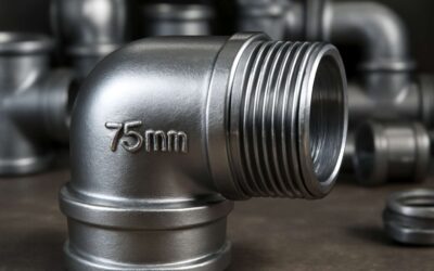
For example, a 90-degree elbow typically results in a higher friction loss coefficient compared to a gentle, sweeping bend. Plumbers and engineers can utilize the pipe fitting friction loss table to compare how different shapes and angles affect resistance. Here’s a quick overview:
- Straight fittings generally cause minimal flow disruption.
- Sharp angles significantly increase turbulence and friction loss.
- Gradual curves are preferred to maintain smooth flow and reduce energy costs.
By selecting fittings with optimized angles and shapes, professionals can better control pressure drops and improve overall system efficiency. The pipe fitting friction loss table simplifies these choices, providing clear data to guide design and installation decisions. Remember, even minor adjustments in fitting angles can lead to substantial differences in friction loss—making this table an indispensable resource in advanced piping system planning.
Pipe Material and Surface Roughness – Influence on resistance and friction
In the intricate dance of fluid dynamics within piping systems, the material and surface roughness of pipe fittings exert a profound influence on resistance and friction. A shiny, smooth surface might seem like an advantage, but in reality, even minor imperfections or roughness can escalate friction loss significantly. This is where the pipe fitting friction loss table becomes an invaluable tool, offering a detailed map of how different materials and finishes impact flow efficiency.
For example, fittings made from cast iron typically have higher surface roughness compared to those crafted from polished copper or stainless steel. Such differences manifest as increased resistance, which can be precisely quantified using the data within the pipe fitting friction loss table. When selecting fittings, it’s crucial to consider these variations, as they directly affect pressure drops and energy consumption. To better understand the influence of surface roughness, consider these factors:
- Material composition and manufacturing process
- Surface finishing techniques
- Corrosion and buildup over time
By evaluating these elements alongside the friction loss coefficients listed in the pipe fitting friction loss table, professionals can optimize system design—reducing costs and enhancing longevity. The subtle nuances of pipe material and surface roughness might seem minor, but they wield significant power in dictating the overall efficiency of fluid transport. Embracing this knowledge ensures smarter, more sustainable piping solutions across South Africa’s diverse infrastructure landscapes.
Benefits of Using a Pipe Fitting Friction Loss Table
Enhanced System Efficiency – Reducing energy costs by accurate calculations
Optimizing piping systems isn’t just about fancy fittings or sturdy materials; it’s about precision—down to the tiniest friction coefficient. A well-crafted pipe fitting friction loss table acts as the secret weapon for engineers and plumbers alike, transforming guesswork into calculated certainty. When energy costs soar higher than a Johannesburg summer, accurate friction loss data can save a fortune by reducing unnecessary pump work and electrical consumption.
By leveraging a comprehensive pipe fitting friction loss table, you gain the ability to predict pressure drops with uncanny accuracy. This means system efficiency skyrockets, ensuring that water or air flows smoothly without choking or surging. Fittings like elbows and tees, often the culprits behind turbulence, are clearly mapped in these tables. The result? Less wasted energy, longer system lifespan, and happier clients who think you’re some kind of piping wizard.
Improved System Reliability – Preventing pressure drops and system failures
In piping systems, even the smallest pressure drops can spell the difference between a smoothly functioning setup and costly failures. When pressure drops unexpectedly or system failures occur, it’s often the unseen friction that’s at fault. A well-utilized pipe fitting friction loss table acts as the silent guardian, providing precise data that prevents these issues before they happen. By accurately predicting how fittings like elbows, tees, and reducers influence flow, engineers can design systems that maintain optimal pressure and flow rate, ensuring reliability from start to finish.
Using a pipe fitting friction loss table offers a strategic advantage—allowing for meticulous planning and troubleshooting. It helps identify potential choke points and turbulence sources, which, if left unchecked, could lead to system failures or inefficient operation. For example, understanding how a sharp-angled elbow affects pressure stability can be the difference between a resilient pipeline and one prone to leaks or bursts. When pressure drops are controlled and predictable, system longevity and safety are significantly enhanced, making the entire installation more dependable and resilient in the face of demanding conditions.
Streamlined Design Processes – Facilitating quick and accurate system planning
In the intricate world of piping design, efficiency is often dictated by how seamlessly each component integrates into the entire system. A pipe fitting friction loss table emerges as an invaluable asset, transforming complex calculations into swift, reliable insights. When engineers harness this data, they can streamline the entire design process, ensuring that every fitting—from elbows to reducers—fits perfectly within the flow’s delicate balance.
By providing precise friction loss coefficients and flow rate ranges, the pipe fitting friction loss table allows for rapid adjustments, reducing the time spent on trial and error. This not only accelerates project timelines but also enhances accuracy, ensuring optimized system performance from the outset. When every turn and junction is accounted for with clarity, the result is a harmonious system that minimizes unnecessary resistance and energy expenditure, making the entire operation more elegant and resilient.
Moreover, the strategic use of a pipe fitting friction loss table elevates troubleshooting capabilities. It reveals potential choke points and turbulence sources before they manifest as costly failures. As a result, system reliability is bolstered, and costly downtime becomes a thing of the past. When flow velocity and volume are meticulously calibrated with this data, the promise of a flawless, long-lasting pipeline becomes an attainable reality—an achievement that underscores the true artistry of engineering.
Common Applications of Pipe Fitting Friction Loss Tables
HVAC System Design – Designing efficient heating, ventilation, and air conditioning systems
In the intricate world of HVAC system design, understanding the nuances of pipe fitting friction loss tables can make all the difference between efficiency and expensive inefficiency. These tables serve as a vital compass, guiding engineers through the labyrinth of fitting types and their impact on fluid dynamics. When designing heating, ventilation, and air conditioning systems, precise friction loss calculations ensure that air and water flow smoothly, reducing energy consumption and preventing costly system failures.
Every component, from elbows to reducers, adds a layer of resistance that can silently erode system performance. By consulting a detailed pipe fitting friction loss table, professionals can anticipate pressure drops and optimize pipe diameters accordingly. This meticulous approach not only streamlines the design process but also unlocks a new level of reliability and efficiency. It’s almost like deciphering a secret code—one that reveals the hidden pathways to system perfection, especially critical in the diverse climate conditions of South Africa.
Industrial Piping – Optimizing flow in manufacturing and processing plants
In the complex choreography of industrial piping, every twist, turn, and subtle bend whispers a story of resistance. The pipe fitting friction loss table stands as a silent sage, revealing how each fitting—be it an elbow, tee, or reducer—imposes its own unique challenge to fluid motion. When harnessed with finesse, this knowledge transforms chaos into harmony, ensuring that manufacturing and processing plants in South Africa operate with the grace of a well-oiled machine.
Understanding the nuances of the pipe fitting friction loss table allows engineers to anticipate pressure drops and fine-tune pipe diameters with precision. This is especially vital in environments where the flow of water or other fluids must be meticulously controlled to prevent costly inefficiencies. Whether it’s optimizing flow rates or selecting the right fitting shape to minimize turbulence, the insights gleaned from these tables serve as a guiding star in the labyrinth of industrial piping.
Water Supply and Plumbing – Ensuring adequate pressure and flow in residential and commercial systems
In water supply and plumbing systems across South Africa, ensuring consistent pressure and reliable flow is essential for both homes and commercial buildings. The pipe fitting friction loss table acts as a vital tool, providing detailed insights into how different fittings influence fluid movement. Whether installing a new system or maintaining existing infrastructure, understanding the friction loss associated with elbows, tees, reducers, and couplings helps prevent unexpected pressure drops.
By referencing the pipe fitting friction loss table, plumbers and engineers can accurately estimate pressure losses caused by various fittings. This knowledge allows for precise adjustments in pipe diameters or flow rates, making sure that water reaches every corner with adequate force. When designing complex plumbing layouts, this table becomes an indispensable resource—helping to streamline processes and ensure system longevity in South African environments.
Tips for Accurate Use of Friction Loss Tables
Match Fitting Types Precisely – Selecting the correct table data for fittings used
Ensuring accurate use of a pipe fitting friction loss table is vital for maintaining the integrity of a piping system. One of the most common pitfalls is mismatching fitting types with the corresponding table data. For example, using an elbow friction coefficient when working with a tee fitting can lead to underestimating pressure drops, which might cause system inefficiencies down the line.
To match fitting types precisely, it’s essential to identify the exact shape and angle of each fitting, then consult the correct section of the pipe fitting friction loss table. This careful step guarantees that the calculated friction loss reflects real-world conditions, saving time and resources during installation. Remember, the slightest mismatch can ripple through the entire system, impacting flow velocity and energy consumption.
While navigating the table, pay close attention to the flow rate ranges and the units of measurement—these can vary widely and influence the accuracy of your calculations. Whether you’re designing an HVAC setup in South Africa or optimizing industrial piping, matching fitting types with their specific friction loss data is the cornerstone of a reliable, efficient system. This meticulous approach not only enhances performance but also extends the lifespan of the entire piping network.
Account for Installation Factors – Bends, changes in diameter, and fittings combined
In any piping system, the tiniest detail can make a significant difference—especially when it comes to friction loss. When installing or maintaining pipelines in South Africa, factoring in installation factors like bends, changes in diameter, and fittings is crucial for system integrity. Overlooking these elements can lead to unexpected pressure drops, increased energy costs, and even system failures. That’s why a thorough understanding of the pipe fitting friction loss table is indispensable for engineers and technicians alike.
To account for these variables accurately, it’s essential to examine how different fittings and pipe modifications interact. For instance, a sudden change in diameter or a complex bend can compound friction loss, making flow less efficient. Incorporating these considerations into your calculations ensures a more reliable and energy-efficient system.
- Assess the specific type of fitting—elbows, tees, reducers, or couplings—since each has unique friction coefficients listed in the pipe fitting friction loss table.
- Consider the cumulative effect of multiple fittings and changes in the piping layout, which can significantly increase overall head loss.
- Factor in the flow velocity, as higher speeds amplify the impact of installation factors on friction loss.
By meticulously integrating these installation factors into your calculations, you create a piping system that performs reliably under real-world conditions. Whether designing for industrial applications or plumbing systems in South African homes, paying close attention to these details can save you time, resources, and future troubleshooting headaches. Remember, the devil is in the details when it comes to friction loss—and a well-informed approach ensures your piping network stands the test of time!
Use of Software Tools – Leveraging software for complex calculations
Utilizing a pipe fitting friction loss table with precision can be the difference between a smoothly flowing system and one plagued with inefficiencies. In complex piping networks, especially within South African industrial settings, relying solely on manual calculations can be a gamble. That’s where software tools come into play, transforming intricate data into clear, actionable insights. These digital solutions can process multiple variables—fitting types, flow velocities, pipe materials—quickly revealing how each element impacts overall pressure drops.
Leveraging software for complex calculations not only enhances accuracy but also streamlines the design process. As you input specific data—such as the friction coefficients for elbows, tees, reducers, or couplings—the program automatically adjusts for installation factors, including bends or diameter changes. This precision ensures your system’s integrity and efficiency. Remember, the key is to match fitting types precisely with the data in your pipe fitting friction loss table, preventing costly oversights and optimizing system performance. Embracing these tools elevates your project from guesswork to certainty, saving time and resources in the long run.
Resources and Tools for Pipe Fitting Friction Loss Calculations
Online Friction Loss Tables – Sources and repositories for free and paid data
In the world of piping systems, having quick access to reliable resources can make all the difference. When calculating pipe fitting friction loss, knowing where to find accurate data is vital for ensuring efficiency and safety. Fortunately, there are numerous resources and tools available online that provide comprehensive friction loss tables—both free and paid—that simplify complex calculations. These repositories serve as invaluable assets for engineers, plumbers, and HVAC specialists alike, streamlining the process of designing and optimizing piping networks.
Online friction loss tables are often hosted by industry associations or specialized software providers. They compile extensive data on fitting types, coefficients, and flow rate ranges, all accessible with just a few clicks. For those seeking more tailored solutions, paid platforms often include advanced features such as customizable parameters and detailed system simulations. Moreover, some websites offer downloadable pipe fitting friction loss table resources that integrate seamlessly with CAD programs or piping design software, enhancing accuracy and productivity.
- National Pipe Fitting Associations
- HVAC and plumbing software vendors
- Industry-specific repositories and databases
- Commercial data providers offering premium content
Whether opting for free online friction loss tables or investing in paid tools, these resources are essential for precise system planning. They help professionals match fitting types with appropriate data, account for installation factors, and optimize flow velocities—all crucial steps in delivering reliable and efficient piping solutions across South Africa and beyond.
Pipe Fitting Manuals – Manufacturer catalogs and engineering handbooks
In the labyrinthine world of piping systems, where precision and efficiency reign supreme, the role of pipe fitting friction loss table is nothing short of legendary. These invaluable resources serve as the compass guiding engineers and plumbers through the intricate maze of fittings, ensuring that every bend, tee, and reducer contributes to a harmonious flow. For professionals in South Africa, the importance of accessing accurate pipe fitting friction loss table data cannot be overstated; it is the key to unlocking optimal system performance and safeguarding against costly failures.
Many manufacturers and engineering handbooks offer comprehensive pipe fitting friction loss tables that detail coefficients, flow rate ranges, and fitting specifications. These manuals, often woven into manufacturer catalogs, provide a treasure trove of information designed to streamline the design process. Whether you’re designing a water supply network or an HVAC system, having the right data at your fingertips simplifies complex calculations and enhances reliability. For those seeking to elevate their system design, these manuals serve as an essential resource, transforming daunting calculations into manageable tasks.
Some of the most revered pipe fitting friction loss table sources include industry-specific repositories, such as those maintained by national associations, and software vendors specializing in piping systems. These repositories often feature detailed diagrams, fitting angles, and surface roughness data, making it easier to interpret coefficients and adjust for installation nuances. When combined with advanced software tools, these tables become a powerful ally in crafting piping networks that are both efficient and resilient—saving energy and reducing wear over time.
Calculation Software – Tools to automate friction loss and system head calculations
In the dynamic realm of piping engineering, harnessing the power of calculation tools can turn what seems like an arcane ritual into an almost effortless craft. Modern calculation software—an essential resource—automates the complex process of determining friction loss and system head calculations, freeing engineers from tedious manual computations. These tools tap into extensive databases, often embedded with up-to-date pipe fitting friction loss tables, to deliver quick, reliable results that streamline system design. With just a few clicks, you can simulate different scenarios, adjusting for pipe material, diameter, and fitting types, all while ensuring your system maintains optimal pressure and flow.
Many advanced software solutions incorporate features such as:
- Real-time adjustments for fitting angles and surface roughness
- Compatibility with industry-standard pipe fitting friction loss tables
- Visualization of flow velocities and potential pressure drops
This integration means that whether you’re designing a water supply network or an HVAC system, you’re equipped with precise data that ensures efficiency and resilience. Leveraging these tools not only enhances accuracy but also accelerates the design process, allowing professionals in South Africa to meet tight deadlines without sacrificing quality. The synergy between cutting-edge calculation software and comprehensive pipe fitting friction loss tables empowers engineers to craft piping systems that stand the test of time and demand, all while optimizing energy consumption and operational costs.

0 Comments