Understanding Pipe Fitting Measurements
Nominal Pipe Size and Actual Sizes
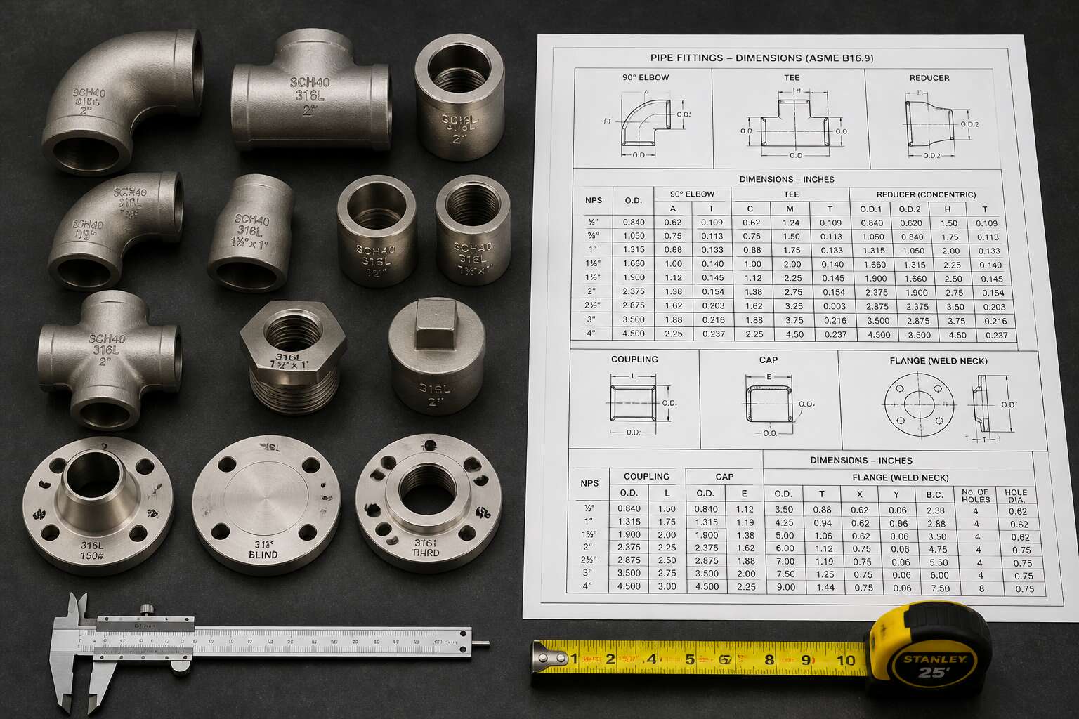
Nominal Pipe Size rarely equals the physical measurement. A 1 inch NPS pipe measures 1.315 inches outside diameter. Contractors in South Africa often discover this mismatch during installations. The pipe fittings dimensions chart provides the actual values behind these labels.
- NPS 1/2 carries an actual outside diameter of 0.840 inches
- NPS 3/4 carries an actual outside diameter of 1.050 inches
- NPS 1 carries an actual outside diameter of 1.315 inches
Wall thickness shifts the inside diameter further. Schedule ratings add confusion. When you pull up a pipe fittings dimensions chart, note that NPS refers to the outside diameter for sizes above 12 inches. Under that, the numbers drift from physical reality. I have seen leaky connections stem from assuming the nominal size matches the fitting. Trust the chart, not the label!
Wall Thickness and Schedule Numbers
Ask any plumber in Johannesburg about schedule numbers and you will likely get a story. The wall thickness of a pipe is stamped with these numbers, but the schedule number itself is not a measurement in millimetres. It is a ratio tied to the nominal size. A Schedule 40 pipe in NPS 2 carries a different wall thickness than a Schedule 40 pipe in NPS 6. That distinction matters when you are selecting the right component.
The pipe fittings dimensions chart shows separate columns for schedule numbers, inside diameter, and wall thickness. The outside diameter remains fixed for each nominal size. Only the wall changes. Thicker walls shrink the inside diameter and raise the pressure rating. Thinner walls lower cost and weight but reduce durability.
The schedule numbers follow a logic: a higher number means a thicker wall. Yet the actual millimetre value shifts across sizes. This is why reading the chart row by row matters.
Outside vs. Inside Diameter
Outside diameter is fixed. Inside diameter changes. The label on a pipe may suggest volume, but the chart shows what actually fits.
For each nominal size, the outer edge stays the same. The wall thickness shifts, which changes the inner bore. Two pipes with identical outside measurements can carry different amounts of water. That difference becomes obvious only when you compare the correct numbers.
Look for three values:
- outside diameter
- inside diameter
- wall thickness
Those three appear together in a proper pipe fittings dimensions chart. Without all three, a fitting can look correct and still fail.
Essential Terminology for Reading Sizing Data
Male, Female, and Universal Threads
Few numbers in a pipe fittings dimensions chart cause as much confusion as those describing threads. Before you attempt any measurement, you must determine whether the fitting is male, female, or universal. A male thread wraps around the outside of the pipe. A female thread sits inside the fitting. Universal threads, often found on garden taps, work with both fixed and flexible connections, but only when you match the right pairing.
These distinctions appear in the sizing columns as abbreviations:
- M or F indicates the thread gender.
- U points to a universal pattern.
- A number such as 14 or 11 denotes the thread pitch in threads per inch.
When you scan a pipe fittings dimensions chart, locate the thread designation first, then worry about the rest. Identifying male, female, and universal threads correctly prevents you from buying the wrong connector. Even experienced installers sometimes misread the small print. Try to measure one with a pair of calipers and you will see why!
Tapered Threads and Sealing Mechanisms
Pipe leaks often trace back to the thread rather than the pipe wall. Tapered threads wedge themselves into the mating piece. The NPT or BSPT designation on a pipe fittings dimensions chart tells you the taper angle and thread form. One degree of taper changes the seal entirely.
Sealing happens at the flank, not the tip. When you tighten a tapered connection, the crests and roots compress together. That metal-to-metal contact blocks leakage. PTFE tape and pipe dope fill gaps; they do not create the seal.
Remember when reading a pipe fittings dimensions chart:
- Thread engagement length determines how much taper overlaps.
- Shallow engagement leaks under pressure.
- Over-tightening distorts the thread and cracks the fitting.
A straight thread with a parallel pitch never achieves that wedging effect. A mismatched taper designation fails under pressure before the seal settles.
Elbow Angles and Center-to-Face Dimensions
An elbow angle is more than a bend; it defines the entire hydraulic path. The pipe fittings dimensions chart lists each elbow by its nominal size and its center-to-face measurement, the distance from the centerline of the opening to the flat face of the fitting. This figure determines how much space the fitting occupies in the run.
Center-to-face values change with the angle. A 90 degree elbow reaches farther than a 45 degree elbow of the same nominal size. The chart also records the radius, tight or long, which alters the flow and the clearance.
- A 45 degree elbow gives a gentle turn with a shorter center-to-face.
- A 90 degree elbow creates a sharp change with a longer center-to-face.
- A long radius elbow increases the center-to-face dimension to reduce turbulence.
Read these numbers carefully. A mistaken center-to-face value offsets the entire assembly, pushing the joint out of alignment before you ever thread a pipe.
Reducing vs. Equal Fittings
A pipe fittings dimensions chart does more than list sizes. It reveals whether a fitting is equal or reducing, and that distinction changes every measurement you read. Equal fittings have identical openings on both ends. Reducing fittings, sometimes called reducers or bushings, join two different nominal sizes.
- Concentric reducers keep the centerline aligned.
- Eccentric reducers offset the centerline to prevent trapped air.
- Reducing tees branch from a larger run to a smaller outlet.
The chart records each side separately, so you must match the larger port to the upstream line and the smaller port to the downstream line. Reading these tables requires care. A reducing tee carries three sets of numbers, one for each branch. Mixing them up turns a simple installation into a leak nightmare. Always confirm which end the chart labels as the run and which as the outlet, because that single detail shapes the whole assembly!
Flange and Union Dimensions
One misread bolt circle diameter can shut down an entire plant. I have watched engineers trip over that number more often than they would admit. Flange and union dimensions demand careful reading. When you open a pipe fittings dimensions chart, you will encounter face-to-face, hub length, and bore diameter. These determine how a component seats against its neighbour. Flanges add bolt circle, number of holes, and flange thickness. South African engineers often work with PN ratings, so the chart pairs each flange with its pressure class. Unions require a different eye. They list seat type and union nut size, because the nut pulls the two ends together.
Essential terms to decode:
- Face-to-face: total length between mating surfaces.
- Hub length: the straight portion that accepts the pipe.
- Bolt circle diameter: measured across opposite hole centres.
Every dimension on that pipe fittings dimensions chart answers a question about fit. The terminology gives each number its meaning.
Industry Standards and Unit Systems
Imperial vs. Metric Sizing Systems
Every year, mismatched unit systems cost South African engineering firms millions in rework. The Imperial inch and the Metric millimetre do not align neatly, and the result is confusion when reading a pipe fittings dimensions chart. Global standards such as ISO 6708 attempt to reconcile the two, but local specifications often override them.
Compare a 2 inch nominal bore to a DN50. They are close, but not identical, and the difference grows with larger sizes. This is why a reliable pipe fittings dimensions chart must clearly state which unit system it follows.
- Wall thickness schedules vary between ASME and EN standards.
- Face-to-face dimensions for flanges differ under each system.
- Tolerance classes are not always interchangeable.
The interplay of imperial and metric sizing creates hidden errors. Without a chart that flags the origin of every dimension, you risk assembling a system that looks correct on paper but fails under pressure. Keep the unit standard visible, always.
ASME, ASTM, and ISO Standards
Three standards bodies govern the fittings trade in South Africa: ASME, ASTM, and ISO. Each publishes its own pipe fittings dimensions chart. They share vocabulary but not mathematics. ASME sets pressure ratings and bolting patterns. ASTM governs material composition and tensile limits. ISO standardises nominal sizes across continents.
Think of the Johannesburg fabricator who reads an ASME chart but receives ISO components. The difference hides in flange thickness and bolt circle diameter. Those millimetres decide whether a gasket seals or leaks!
- ASME B16.5 covers flanges and fittings to 24 inches.
- ISO 7005 adapts those dimensions to metric.
- ASTM A105 dictates carbon steel material quality.
Engineers who ignore the source of each dimension assemble systems with elegant drawings and poor pressure tests. The pipe fittings dimensions chart that does not identify its standard is a trap. Read the header before you measure.
Pressure and Temperature Ratings
Pressure ratings are the arithmetic of failure. A pipe fittings dimensions chart rarely whispers why a flange holds at 40 bar yet weeps at 120 degrees Celsius. The answer lives in unit systems and their temperature scales, which shift the numbers before they reach the shop floor.
In South Africa, the engineer juggles PSI and bar, Fahrenheit and Celsius. Each conversion carries a rounding error that accumulates into gasket stress. Consider these realities:
- Carbon steel loses tensile strength above 200 degrees Celsius.
- Stainless ratings change with heat treatment, not just wall schedule.
- A pressure rating without a temperature reference remains incomplete.
The pipe fittings dimensions chart must state its temperature base. Without it, the dimension table offers only geometry, not safety.
Material-Dependent Variations
A dimension is one part of a specification. The same nominal size in carbon steel and duplex stainless obeys different standards, each with its own tolerances and unit conventions. A pipe fittings dimensions chart that ignores these distinctions is a snapshot, not a working document.
- ASTM A234 for wrought carbon steel fittings
- ASTM A403 for stainless steel fittings
- ISO 4144 for threaded stainless fittings
South African engineers juggle British and European standards, moving from inches to millimetres. Material-dependent variations in hardness, corrosion allowance, and heat treatment affect how dimensions hold under service. The chart must state its material base.
How to Measure Fittings Accurately
Tools and Instruments Needed
Precision in pipe fitting measurement begins with selecting the right instruments. A vernier calliper offers resolution down to 0.02 millimetres, while a thread pitch gauge identifies the exact thread count per inch. For larger diameters, a flexible tape measure wrapped around the pipe gives the circumference, which you divide by pi to obtain the outside diameter. A digital calliper simplifies readings for tight spaces.
To verify depths and socket dimensions, use a depth gauge or a simple steel ruler. Always confirm your measurements against a reputable pipe fittings dimensions chart before cutting or ordering components. The chart resolves discrepancies between nominal sizes and actual values.
I recommend these tools:
- Vernier or digital callipers
- Thread pitch gauge
- Flexible steel tape
- Depth gauge
Step-by-Step Measurement Process
Even a half-millimetre error can cause a joint to leak or a fitting to fail under pressure. Precision requires a methodical approach. Start by cleaning the pipe end thoroughly, since dirt and corrosion distort every measurement you take.
Proceed through these steps:
- Measure the outside diameter with a vernier calliper at two separate points, then average the values.
- Count the threads per inch using a thread pitch gauge to identify the thread standard.
- Insert a depth gauge into the socket until it rests against the shoulder, and record the depth.
Collecting these figures gives you the raw data. The decisive step is comparing them against a pipe fittings dimensions chart. That chart reveals the actual fitting size, schedule, and thread type, preventing expensive mismatches.
Measuring Threaded vs. Welded Fittings
Roughly forty percent of fitting failures trace back to the measuring instrument, not the welder’s torch. I have seen this pattern in South African workshops. Threaded and welded fittings require different measurement methods because each transmits pressure through different geometry.
Threaded fittings demand verification of pitch, taper angle, and effective thread engagement. The chart shows nominal size, but actual engagement depth changes the connection’s integrity. Welded fittings are different! Socket depth determines the insertion mark, and the bevel at the mouth influences the weld pool.
The pipe fittings dimensions chart resolves both cases when the data is correct.
- Threaded: pitch, diameter, engagement.
- Welded: socket depth, bevel, insertion mark.
Without a precise profile of each end, the chart becomes guesswork.
Common Errors and How to Avoid Them
Every measurement begins with a tool that must be trustworthy. When the caliper is dirty or the eye looks down at an angle, the reading is already compromised. I have seen rushed readings and unzeroed instruments in South African workshops.
Move deliberately! Wipe the measuring faces clean. Confirm the zero point before every session. Take three readings and record the average. The pipe fittings dimensions chart interprets your numbers, but it cannot correct a false reading.
Common errors to avoid:
– Reading the scale from the side instead of straight on.
– Squeezing the caliper jaws until the metal flexes.
– Trusting a stretched tape measure just because it looks intact.
Interpreting Manufacturer Markings
Once the caliper has delivered its numbers, the fitting itself still carries a set of manufacturer markings. These stamps are a compact record of the component’s origin.
- Batch numbers reveal the casting run.
- Standard stamps point to the governing specification.
- Arrow marks indicate flow direction where orientation matters.
To measure accurately, align the physical reading with these stamps. The pipe fittings dimensions chart translates both the calibrated size and the manufacturer’s abbreviation into a complete identity. A mismatch between the stamped schedule and the measured wall thickness signals a counterfeit or a recycled part. South African workshops often find that the mark is faded, yet even a partial imprint can be matched to the chart. Read the marking under direct light, and treat every symbol as a piece of evidence.
When to Consult a Professional
The distance between a correct measurement and a costly guess is often less than a millimetre. A caliper reading means little if you misread the thread pitch. I take three measurements, rotate the component, and record the smallest value. Consistency wins! That number only gains meaning against the pipe fittings dimensions chart. It tells you whether a 48.3 mm outside diameter belongs to a DN40 or a DN50, and flags inconsistencies before leaks.
When should you stop measuring and call in a professional? Certain situations demand a second pair of eyes:
- Unusual wear patterns that alter the original dimensions
- Corrosion that has pitted the surface beyond clean measurement
- Fittings that fail to seat despite matching the chart
If your readings conflict across multiple samples, or if the installation involves high pressure steam lines, call a certified plumber or engineer. They can interpret the pipe fittings dimensions chart alongside your physical samples.
Applying Data Tables to Real Projects
How to Read Column Headers and Rows
Reading a pipe fittings dimensions chart begins with understanding that columns are a fixed set of parameters, while every row represents one specific fitting configuration. Ask yourself what you need to solve. The header row tells you which measurement matters, such as center to face or seat depth. Then trace the row for your nominal size and wall schedule.
I often see professionals skip the header and jump straight to a number, which leads to costly errors. For real projects, the chart becomes a map. You locate the intersection of two facts.
- Identify the standard, since ASME and ISO may order columns differently
- Confirm the column unit, whether millimetres or inches
- Read the row as a complete set, not isolated values
That discipline turns a dense table into a usable specification. The pipe fittings dimensions chart earns its place when you treat each row as a promise about thread type, bore diameter, and face distance all at once.
Cross-Referencing Compatible Components
When you move from reading a pipe fittings dimensions chart to applying it, the real work begins. You are no longer scanning rows for a single measurement. You are comparing multiple components against each other to confirm they function as one assembly.
A typical project might require a threaded reducer, a 45 degree elbow, and a ball valve. Each component has its own row in the pipe fittings dimensions chart. The challenge is verifying that the bore diameters align and the face distances fit your layout. Cross-referencing means checking those values side by side before you order anything.
The process follows a set order:
1. Confirm the schedule number matches across every component.
2. Verify the thread type is identical for each connection point.
3. Compare the center to face dimensions for elbows against your available space.
That discipline prevents mismatched assemblies and wasted material.
Accounting for Tolerances and Clearances
When the dimensions chart gives you a nominal measurement, the real world rarely matches it exactly. Manufacturing tolerances allow for slight deviations, and those fractions of a millimetre affect how components nest together. That gap matters when you are welding or threading in tight corners.
Clearances are just as critical. You need room for a spanner to tighten a union, space for a flange to be bolted, and access for a welder’s torch.
- Allow extra space for pipe insulation.
- Check the swing radius of a lever handle.
- Account for thermal expansion in hot lines.
In South African installations, these allowances are not optional. A pipe fittings dimensions chart is a starting point; the tape measure on site remains the final authority.
Double-Checking Your Calculations
The pipe fittings dimensions chart is a noble piece of paper, but it has never stood in a muddy trench in Gauteng. I have learned that the table offers a suggestion, not a promise. When I moved a 65 mm branch line last month, the chart said one thing, the actual flange said another, and the two disagreed by just enough to annoy me. That is why I verify every calculation against the physical component before welding. The chart is my starting point, the steel parts are my final authority.
Real projects punish assumptions. A colleague once ordered all his fittings from the table, then watched the site foreman wave a tape measure at the delivery. Nothing matched! A pipe fittings dimensions chart earns its keep when you use it to check, not to guess.

0 Comments