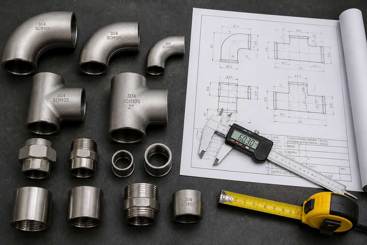
Understanding Pipe Fitting Measurements
Why Accurate Measurements Matter
One millimetre of error can cause a pipe joint to fail under pressure. In South Africa, where water scarcity demands efficient distribution, precision is essential. A pipe fitting dimensions chart records every critical value, from nominal bore to thread pitch, ensuring that components align perfectly.
Accurate measurements prevent costly rework and dangerous leaks. When I inspect a fitting, I verify the actual diameter against the chart’s specification. This habit saves time and protects lives. Small discrepancies in wall thickness or angle can compromise an entire system, so trust the chart, not guesswork.
Common Measurement Units (Inches, Millimeters)
South African plumbers handle both metric and imperial measurements daily. Our specifications demand millimetres, yet many imported fittings are stamped in inches. The pipe fitting dimensions chart reconciles both systems. It does not simply multiply by 25.4. That crude conversion fails when thread forms and wall thicknesses enter the equation. A 15mm nominal bore is not a true equivalent to 1/2 inch. The chart records the exact external diameter, the thread pitch, and the pressure rating for each standard.
Consider the common sizes you will encounter on a typical installation:
- 15mm and 1/2 inch, close but not identical in outside diameter
- 22mm and 3/4 inch, frequently mismatched on site
- 28mm and 1 inch, where the difference becomes dangerous
I always check the pipe fitting dimensions chart before ordering. It prevents the failure of a fitting that looks correct but seats poorly. Manufacturers often stamp both values on the body, but those markings are not always reliable. The chart remains the authoritative reference. A quick glance at the millimetre column saves an afternoon of rework.
Nominal Pipe Size (NPS) vs. Diameter
A nominal pipe size is a label, not a measurement. The 15mm pipe on a South African rack may carry an NPS designation that suggests a different physical reality. The pipe fitting dimensions chart reveals the actual outside diameter, which diverges from the nominal value in ways that surprise even seasoned plumbers.
NPS originated as a North American standard, yet it travelled the world on imported fittings. A 1/2 inch NPS pipe has an outside diameter of 21.3mm, while its South African counterpart is marked 15mm. The nominal size describes a legacy dimension, not the metal I hold in my hand.
The confusion persists daily:
- NPS references the approximate inside diameter, which shifts with wall thickness
- Outside diameter stays constant for each NPS size
- Schedule ratings change the wall, but never the outer dimension
The pipe fitting dimensions chart records these relationships. Without it, a fitting that looks correct can fail at the thread.
Wall Thickness and Schedule
A schedule number states how much metal a pipe truly carries. Two pipes with the same outside diameter can lead entirely different lives. A Schedule 40 15mm pipe handles pressure that would strain a Schedule 10 version. Yet both fit the same elbow externally. Only the pipe fitting dimensions chart tells you what you actually hold before you cut.
Schedule values follow a simple arithmetic. Higher numbers mean thicker walls.
- Schedule 10 suits low pressure and light duty.
- Schedule 40 handles standard residential and commercial loads.
- Schedule 80 serves heavy industrial needs.
Mixing schedules on one line creates quiet hazards. The outside fit looks correct, so the connection engages, but internal volume tightens as the wall thickens. Water pressure, flow rate, and thermal transfer all shift. The dimensions chart records these distinctions with cold precision.
Standard Dimensions for Common Fittings
Elbow Fittings (90°, 45°)
A 90° elbow bends flow with a precision that often surprises. The centre to face measurement, not the outer diameter, defines its placement. On any reliable pipe fitting dimensions chart, you will find this value listed for each nominal pipe size. For 90° elbows, the long radius pattern equals 1.5 times the NPS. The 45° version shares the same face to centre logic, but the radius calculation shifts.
I find the numbers telling. For NPS 2, a 90° long radius elbow measures 76 mm from centre to face. A 45° elbow of the same size sits at 31 mm. Short radius options compress the 90° to 51 mm. These differences matter when you are threading through tight spaces, especially in retrofit work.
Tee Fittings
Tee fittings split flow in three directions, which makes their dimensions a different kind of challenge. Unlike elbows, a tee has two centres to measure: one for the run and one for the branch. The run uses the same centre to face logic as other fittings, but branch height depends on whether you have an equal or reducing tee.
Equal tees, with all three openings at the same nominal size, are the standard. Reducing tees complicate things. The branch outlet drops to a smaller NPS, but the branch height may not shrink proportionally. That is where a reliable pipe fitting dimensions chart earns its keep.
A few common measurements:
- The centre to face dimension is typically the same as a matching elbow.
- The branch outlet dimension varies by manufacturer and schedule.
- Threaded and socket weld tees use different face measurements than butt weld versions.
Verify the branch height against the pipe fitting dimensions chart before ordering.
Couplings and Unions
The same pipe fitting dimensions chart that guides your tee selection also settles coupling and union dimensions. A coupling that leaks is almost always a dimension problem, not a material problem. I have replaced enough of them to know. The face to face length determines how much thread engagement each pipe receives. A short coupling on a high pressure line is a weak point. Unions add another variable. They are three separate pieces, two end connectors and a central nut. The assembled length and the nut size both matter when you are working in a confined space.
Check these values on the chart before you assemble:
- Face to face length for couplings.
- Overall length for unions when fully tightened.
- Nut size across flats for the spanner.
The chart lists these alongside the nominal bore. A supplier in Johannesburg or Cape Town will expect you to know them.
Reducers and Adapters
A single number separates a perfect joint from a weeping leak. For reducers, that number is the end to end length, which governs the angle of flow convergence. A concentric reducer centers the bore, while an eccentric one sits flush on top to avoid trapping air; the chart lists both the offset and the two port diameters. Adapters demand a different kind of precision. The thread form, either BSP or NPT, must match exactly, and the face length determines how much thread remains exposed.
- Confirm the reducing length for clearance.
- Measure both port sizes.
- Check the thread standard for adapters.
Johannesburg technicians use these values to prevent leaks at the transition point. The pipe fitting dimensions chart is the only reference that never misleads.
Flanges
Flanges demand their own arithmetic. A standard flange is defined by five numbers: the outer diameter, the bolt circle diameter, the number of bolt holes, the bolt size, and the hub thickness. Change any one and the joint will not seat. The pipe fitting dimensions chart must list each value with the same reverence it gives a reducer’s length, because flanges fail quietly.
A PN16 flange and a Class 150 flange are not interchangeable, even with an identical bore. The bolt circle alone tells you which standard governs the connection. The pipe fitting dimensions chart settles these questions before steel is cut. I always verify the flange face finish, since a serrated face grips the gasket, while a smooth face invites extrusion.
- The bolt circle, measured center to center, separates a PN flange from a Class flange.
- The number of bolt holes, often eight or twelve, must match the chart exactly.
- The hub length determines how much pipe the weld can penetrate.
How to Read a Fitting Dimensions Chart
Key Columns and Data Points
One misread column in a pipe fitting dimensions chart can push a pipeline assembly out of alignment by millimetres. I have watched entire batches scrapped over a single copied figure! The table looks plain, yet each header carries a specific engineering intent.
Most charts list nominal bore and outside diameter, but the real differences sit in the dimensional columns. Centre-to-end values define the reach of a directional fitting. Thread engagement length shows how far the male thread enters the socket. Socket depth tells a welder where the pipe must stop inside the joint.
Typical header groups include:
- Centre-to-end (direction control)
- Thread engagement length (connection security)
- Socket depth (weld backing distance)
- Bore path diameter (internal flow opening)
These numbers shift with material grade and pressure class, so identical labels can appear with different values on separate pages of a pipe fitting dimensions chart. Every column only makes sense when matched to the correct fitting type.
Interpreting Tolerances
Reading a pipe fitting dimensions chart is about understanding the gap between what is drawn and what is machined. Tolerances define that gap. A nominal 50 mm bore can measure 49.8 mm or 50.2 mm and still pass inspection. The chart states the permitted deviation, not the ideal number.
Every column carries its own tolerance class. Centre-to-end values might allow ±1.6 mm on a forged elbow, while socket depth holds a tighter band. Match the tolerance to the measuring tool. A vernier is fine for most checks, bore path diameter may need a bore gauge.
- Allowed deviation appears in millimetres or inches
- Heat affected zones change effective dimensions
- Coating thickness eats into the stated bore
In South African workshops, the common error is treating the pipe fitting dimensions chart as absolute. It is a contract of limits, and each limit shifts with pressure rating and material grade. The numbers you see are anchors, not certainties, and the tolerance column tells you how far the anchor can move.
Matching Measurements to Actual Fittings
Reading a pipe fitting dimensions chart on paper is one thing. Holding a caliper to the delivered fitting is another. The chart gives you centre-to-end values, socket depths, and bore limits, but the physical part arrives with its own story. In practice, I compare the chart’s stated dimensions against the fitting in my hand before any pipe gets cut.
Several discrepancies surface regularly when matching measurements to actual fittings:
- Forged elbows often show slight ovality at the ends
- Coating thickness reduces the effective bore beyond the chart’s tolerance
- Threaded fittings measure differently across the crest and root of the thread
The pipe fitting dimensions chart tells you what the manufacturer intended. The fitting itself tells you what the manufacturer shipped. Both matter, but only one gets bolted into your line.
Application-Specific Dimension Considerations
Hydraulic Systems vs. Plumbing
Plumbing and hydraulic systems demand different readings from the same pipe fitting dimensions chart. A domestic water line rarely exceeds 80 psi, while a hydraulic circuit can surge past 3000 psi. That gap changes everything downstream.
Consider the following:
– Hydraulic fittings need higher burst ratings and tighter tolerances for pressure retention.
– Plumbing fittings prioritise corrosion resistance and ease of disassembly.
– Hydraulic systems often require metric or JIC threads, while plumbing leans on BSP or compression.
The schedule numbers, wall thickness, and thread pitch you select all flow from this distinction. Ignoring the application means the pipe fitting dimensions chart becomes a source of error, not guidance.
High-Pressure vs. Low-Pressure Applications
Shipping a pipeline from Durban to a highveld plant means checking the pressure rating against the pipe fitting dimensions chart. A low pressure condensate return at 3 bar allows a thin wall schedule 20. A 200 bar nitrogen line demands a forged fitting with a certified burst limit. For high pressure service, prioritise:
- tensile strength ratings
- fatigue resistance under cyclic loads
- exact thread engagement depth
Low pressure systems instead push you toward corrosion allowances and ease of welding, but the chart still governs outside diameter compatibility. One number, the NPS, stays constant. Everything else changes with the pressure you intend to hold.
Threaded vs. Welded Connections
A welder’s choice between threading and welding is often a quiet decision, but it shapes every maintenance call for a decade. The pipe fitting dimensions chart tells you the outside diameter and the pressure class, yet it does not tell you how the joint will behave under vibration or thermal shock. Threaded connections rely on precise thread engagement length, and a taper that must seat cleanly. Welded connections demand a groove preparation that matches the schedule, but they forgive misalignment better than a thread that has galled.
The dimension chart matters most when you must compare the root diameter of a thread against the bore of the fitting. If the wall thickness is too thin, a thread will cut through the pressure boundary. For welded joints, the same schedule can be joined with full penetration, so the wall remains intact.
Consider what the site conditions require:
– Threaded joints are faster to install and easier to remove, which suits temporary lines.
– Welded joints provide a continuous metal path, reducing leak paths in corrosive environments.
– Threads require lubrication and careful torque, while welds need a qualified artisan.
A rural pumping station often chooses threaded connections for ease, but a highveld plant will weld where the line runs hot. Both approaches start with the same pipe fitting dimensions chart, yet the choice determines the lifespan of every joint. The thread depth or weld profile must suit the actual material thickness, not the nominal size alone.
Material Expansion and Contraction
Heat moves metal. A pipe fitting dimensions chart gives you the cold dimensions, but the line will not stay cold. In the Highveld sun, a carbon steel line can climb past 60 degrees Celsius during the day and drop below freezing at night. That swing changes the length of every straight run.
Expansion and contraction place stress on fittings. The chart tells you the wall thickness and the bore, but it does not tell you how much the material will grow. That depends on the coefficient of thermal expansion for the specific alloy. Stainless steel grows more than carbon steel per degree of temperature change.
- Check the ambient temperature range at the site.
- Calculate the expected movement for each run.
- Select fittings with enough wall thickness to handle the resulting stress.
For a plant that runs hot, the pipe fitting dimensions chart is the starting point. The actual dimensions must account for the thermal cycle, or the joint will fail long before its rated pressure is reached.
Industry Standards (ASME, ASTM, ISO)
ASME B16.11 and ISO 4144 disagree on thread taper for certain pressure ratings. That single decimal shift forces a different gauge on the fitting face. A pipe fitting dimensions chart must state the standard it follows, or the dimension becomes guesswork.
Application specific considerations tighten the margins. Mining slurry lines handle high abrasion, so the internal bore needs a different surface finish. Steam services require scheduled wall thickness beyond the nominal pressure rating. Refineries in the Highveld often specify larger radii on elbow fittings to reduce erosion.
- ASME B16.9 controls buttwelding dimensions
- ASTM A403 sets material tolerances for stainless
- ISO 4144 dictates thread pairing
Each standard changes how you read the chart. For a plant in Sasolburg or Secunda, the right standard means the difference between a joint that holds and one that cracks. Ignore the applicable code and the pipe fitting dimensions chart loses its purpose.
Custom and Metric Fittings
In South Africa, metric fittings dominate municipal and industrial work, but imported equipment often carries imperial dimensions. A pipe fitting dimensions chart must flag both systems clearly. Custom fittings add another layer. A slurry pump in Mpumalanga may need a thicker bore or altered radius that no standard chart lists. Plants in Secunda and Sasolburg routinely mix components from different countries, creating gaps that only bespoke measurements can fill.
Consider these scenarios where stock dimensions fail:
1. Existing pipework with unknown material pedigree
2. Retrofits of older plant infrastructure
3. Non-standard flange face distances
These situations demand field measurements and a fabricator willing to deviate from the chart. Metric fittings follow ISO threads; imperial fittings follow ASME. A single decimal shift changes the joint’s integrity. The pipe fitting dimensions chart remains a starting point, not the final authority.

0 Comments