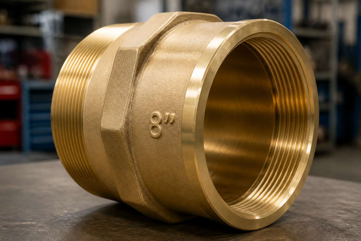
Understanding Large-Diameter Pipe Fittings
What Defines a Large-Diameter Fitting?
A 600 mm water main is unmistakable. The less obvious question is whether an 8 pipe fitting counts as large-diameter at all. Within South African specification practice, the term usually applies from NPS 12 upward, but that rule of thumb misses the engineering reality. An 8 pipe fitting often requires the same wall thickness calculations and stress analysis as much larger components.
- Heavy wall schedules to handle internal pressure
- Specialised welding procedures and qualified welders
- Additional allowance for thermal expansion
- Mechanical lifting assistance on site
In my experience across Gauteng projects, an 8 pipe fitting occupies that boundary zone. It remains manageable by hand, unlike a 300 mm or greater component, yet it carries comparable design burdens. In mining slurry lines and petrochemical installations, this fitting gets specified with the same scrutiny applied to NPS 24 pieces.
Primary Applications in Industrial Piping
Somewhere between a hand-tool component and a rigging operation lies the 8 pipe fitting. It is the pivot point where manual assembly gives way to mechanical lifting, and where standard pressure ratings yield to computational stress analysis. In Gauteng’s industrial corridors, this size often serves as the final manually handled component before the jump to NPS 12 and beyond.
The primary applications for this fitting concentrate in high-pressure process lines where operational continuity is non-negotiable. Slurry handling in mining operations depends on these components to manage abrasive flow rates, while petrochemical plants rely on them for their erosion resistance in critical transfer lines.
Common deployments include:
– High-pressure steam distribution systems
– Acid and chemical transfer piping
– Compressed air networks in manufacturing plants
These applications demand that the 8 pipe fitting comply with the same stringent material traceability as larger siblings. For water utilities, this specific size often appears in pump station manifolds where flow control is crucial. The fitting also features prominently in fire suppression systems where every connection point must guarantee absolute integrity under sudden pressure surges.
How 8-Inch Fittings Differ from Standard Sizes
“A little more bulk, a little more resistance, and a great deal more consideration.” This is the unspoken law of the piping trade when dimensions escalate. The 8 pipe fitting is where this law takes hold with undeniable force. It is not merely a scaled-up version of a smaller component; its physical mass renders the old rules of handling obsolete. The weight alone shifts the dynamic, demanding a respect for gravity that a two-inch worker never contemplates.
The geometry is responsible for this divide. Consider the wall thickness required for the pressure ratings of this class. It creates a stiffness that resists the casual persuasion of a pipe wrench. This is where the differences become operational realities, setting the 8 pipe fitting apart from its smaller brethren in several critical ways:
1. The sheer weight necessitates lifting equipment; it is no longer a one-person operation.
2. The increased cross-sectional area requires a different welding procedure and heat input.
3. The rigidity means that pipe alignment errors are no longer forgiving, they are catastrophic.
This shift from manual handling to mechanical rigging alters the installation sequence entirely. The tactile feedback of a smaller fitting is replaced by the impersonal precision of a crane. For engineers and contractors in South Africa, the transition is a clear line in the sand. Before this size, you are bending metal to your will. At this size, you are negotiating with it. The 8 pipe fitting represents a point of no return, where the human element of the work becomes secondary to the physics of the material.
Types of Fittings for 8-Inch Pipelines
Elbows and Bends for Directional Changes
Anyone who has ever tried to force an 8-inch pipe around a corner without a proper elbow knows the cost of that mistake. The difference between an elbow and a bend comes down to geometry, radius, and sometimes your patience. Elbows are factory-made with fixed angles like 45 or 90 degrees. Bends are custom-curved to follow your specific route, which makes them indispensable for tight industrial spaces across South Africa.
For an 8 pipe fitting, choosing between them depends on flow dynamics and available clearance. Long-radius elbows reduce pressure loss, while short-radius elbows save space but risk turbulence. Custom bends are made on-site, which is fancy until the fabricator mismeasures. These are your primary options:
- Long-radius elbows for gentle flow
- Short-radius elbows for tight corners
- Custom bends for unique angles
After you have selected your turning method, ensure the fitting matches your pipe schedule. Otherwise, you will face leaks or awkward geometry. And nobody wants to explain that to the plant manager.
Reducers and Couplings for Size Transitions
When an 8 pipe fitting meets a smaller line, the reducer manages the transition. Concentric reducers keep the centreline true, which suits vertical risers where flow symmetry matters. Eccentric reducers sit flat on one side, preventing air pockets in horizontal runs. The choice affects the hydraulics directly, not merely the appearance.
Couplings offer a simpler union when diameters match. A threaded coupling screws two pipes together with direct force, while a grooved coupling clamps fast for maintenance crews who value their hours. We see more failures from mismatched pressure ratings than from pipe fatigue. The 8 pipe fitting must match the pipeline’s rating, otherwise you inherit a weak point that surfaces during testing.
Caps and Plugs for System Sealing
Caps and plugs serve distinct roles. A cap seals the end of an 8 pipe fitting, stopping flow entirely. A plug fits into a threaded opening, allowing quick access for pressure tests or drain points. Both must match the system’s rated pressure, otherwise the closure becomes the weakest link.
For permanent sealing, a welded cap offers the most secure bond. For temporary work, a threaded plug with a proper sealant is easier to remove. Temperature shifts cause expansion, so the fitting material needs room to flex.
Flanges and Unions for Easy Disassembly
A piping system designed for permanence is a fine thing, but industry rarely affords such luxury. The true mark of a well considered design is its serviceability, which brings us to the flanged joint. For the 8 pipe fitting, a flange pair offers the distinct advantage of reversibility. You unbolt, you separate, and the line opens for inspection. It is the mechanical equivalent of a proper handshake, firm and respectful, yet never binding.
Unions perform a similar function, though they operate on a smaller stage. A union is a single, compact component that allows for quick disconnect without the hassle of sliding the entire pipe back. This is particularly useful when space is at a premium, or when the primary concern is speed of access. The internal design of these connections requires flat faces and gaskets to be pristine. A scratch here is a leak waiting to happen, a sentiment I find applies to many things in life.
When one selects between these two, consider the frequency of access.
– A flange requires alignment and multiple bolts, which takes time.
– A union is a single nut, tightened with a spanner.
– Flanges are superior for larger pressure ratings.
– Unions are easier to manage in tight, awkward corners.
The choice, as with most things, hinges on your specific requirement for patience versus expediency. However, the bolting pattern on a flanged 8 pipe fitting demands a torque wrench to ensure even pressure. Doing so by feel is an invitation for a catastrophic failure, or at the very least, a slow, irritating weeping that stains the concrete. Use the tool. Your maintenance team will silently thank you.
Material Selection for 8-Inch Piping Systems
Carbon Steel Fittings for High-Strength Applications
Choosing the right material for an 8 pipe fitting demands attention. Carbon steel fittings excel in high strength applications, where pressure and temperature put ordinary metals to the test. Their durability comes from a balanced composition, not from exotic alloys. Weldability matters, especially when field modifications are necessary. You might also consider yield strength, which directly impacts wall thickness requirements. For South African industries, from mining to petrochemicals, carbon steel remains a practical choice.
A quick checklist helps simplify selection:
- Check the pressure rating for your system
- Confirm the carbon content for weldability
- Verify corrosion allowance for your specific fluid
Remember, the 8 pipe fitting you choose must match the pipe schedule exactly. Mismatches create stress points. Proper material selection prevents premature failures, keeping operations running safely.
Stainless Steel Options for Corrosion Resistance
In South Africa, corrosion is never a minor inconvenience. Municipal water quality varies drastically from town to town, and coastal plants face salt-laden air that corrodes standard carbon steel quickly. For an 8 pipe fitting in that environment, stainless steel changes the entire calculation.
Two grades carry most of the workload. Grade 304 handles general chemical and food processing duty. Grade 316 adds molybdenum, giving it resistance to chlorides and sulfur compounds found in industrial effluent. I have seen 8 pipe fitting failures at Durban harbor facilities that came down to specifying 304 instead of 316.
- The fluid running through the line
- The chloride concentration in that fluid
- Whether the fitting is welded on site or pre-fabricated
The choice is not about prestige. Grade 316L costs more per meter. But for a system meant to last twenty years, the upfront premium beats a shutdown!
PVC and CPVC for Chemical and Water Systems
A water treatment facility in Gauteng uses kilometres of PVC. Walk through one and you will see this polymer carrying potable water with little ceremony. Yet PVC has a temperature limit. Beyond 60 degrees Celsius, the material softens and loses its dimensional integrity. Chlorinated polyvinyl chloride, or CPVC, steps in where heat refuses to stay restrained. I have watched engineers pair CPVC with aggressive chemical lines and sleep soundly afterwards!
Consider these factors before committing to a polymer route:
- Operating temperature range
- Prolonged exposure to sunlight, which degrades PVC
- Chemical compatibility with the specific fluid
The polymer decision comes down to service conditions, not price alone. A misstep with an 8 pipe fitting here creates leaks that no flange gasket can remedy.
Ductile Iron and Cast Iron for Heavy-Duty Use
Ductile iron and cast iron carry a different weight. Cast iron has served South African industry for over a century, but fractures under sudden impact. Ductile iron shares the lineage yet adds resilience. Its nodular graphite structure permits deformation under stress instead of brittle failure. For municipal mains and industrial lines, ductile iron withstands ground movement, pressure surges, and heavy soil loads. Consider these traits when selecting an 8 pipe fitting:
- Cast iron: strong under compression, weak under tension
- Ductile iron: tensile strength around 414 MPa, elongation up to 18 percent
- Both need corrosion protection such as cement mortar lining
Ductile iron uses thinner walls than cast iron for equal pressure ratings. I have watched old cast iron mains shatter during earthworks while adjacent ductile iron flexed and survived. South African engineers favour ductile iron for high pressure routes. Cast iron remains for gravity systems where impact risk is low. The choice rests on installation conditions and service demands.
Alloy and Specialty Materials for Extreme Conditions
Elevated temperature and high chloride concentrations destroy standard steel quickly. For aggressive process lines, super duplex stainless steel gives an 8 pipe fitting system a service life that 316L cannot match. Its high chromium and molybdenum content resists pitting and crevice corrosion. Where hydrofluoric or hot sulphuric acid appears, nickel alloys such as Hastelloy handle what ordinary metals cannot. I have specified titanium for seawater and brine handling. For abrasive slurries in South African mines, ceramic lined fittings outlast steel by many months.
A material selection for an 8 pipe fitting accounts for these variables:
- The fluid’s precise chemical composition
- The maximum operating temperature and pressure
- The alloy’s pressure derating at elevated temperatures
- Field welding procedures and site constraints
PFA lined carbon steel fittings offer an alternative, combining structural strength with an inert surface at a fraction of alloy cost.
Sizing, Dimensions, and Pressure Ratings
Understanding Nominal Pipe Size for 8-Inch Fittings
The pressure rating of an 8 pipe fitting is not a fixed number, but rather a story told by its material and wall thickness. For instance, a standard Schedule 40 carbon steel fitting might be rated for roughly 730 psi, yet its Schedule 80 counterpart can handle significantly higher pressures due to its thicker walls. This pressure ceiling hinges entirely on the dimensions of the bore and the material’s tensile strength at operating temperatures.
Nominal Pipe Size, or NPS, is a curious standard, an approximate gauge rather than a precise measurement. For an 8 pipe fitting, the outside diameter is locked at 8.625 inches, but the inside diameter fluctuates based on the schedule. This means the fitting’s physical footprint remains constant for connection purposes, while the internal flow area changes. Furthermore, the pressure rating for socket weld or threaded varieties will differ from flanged or butt weld connections, as each joint type presents a unique mechanical weakness.
When selecting a fitting for exacting work, the specifics demand attention. You must verify the following:
– The specific pressure class or schedule designation.
– The temperature derating factors for your highest operating condition.
– The exact material grade, as cast and forged metals behave differently.
– The end connection type and its specific pressure limitations.
The dimension from the centerline to the face of an 8 fitting elbow is strictly dictated by standards, ensuring it mates perfectly with its pipe. Threading also plays a role, as an 8 pipe fitting cut with NPT threads requires precise length and taper tolerances to ensure a pressure tight seal without stressing the joint. Even the tolerance for ovality in a large diameter fitting is strictly checked; a deviation of just a few thousandths of an inch can compromise the entire integrity of the system.
Wall Thickness and Schedule Considerations
An 8 pipe fitting in schedule 80 weighs more than half again as much as its schedule 40 counterpart. That extra metal is not for show. It is the difference between a system rated for 730 psi and one that can hold beyond 1,000 psi. Wall thickness is the primary lever on pressure capacity.
Thicker walls also shrink the inside diameter. The outer dimension stays locked at 8.625 inches, but the bore narrows. That reduces flow area, which changes pump sizing and fluid velocity. For any 8 pipe fitting, I confirm the internal diameter before connecting to existing pipe.
Schedule alters face-to-face dimensions on elbows and tees. A thicker wall extends the centerline radius, making the fitting physically longer. That complicates tight pipe racks.
Pressure ratings shift with temperature. A fitting rated for ambient conditions may derate by 30% at 200°C. The schedule and material grade dictate the exact ceiling for your system.
Pressure and Temperature Ratings Explained
An 8 pipe fitting rated at 1,000 psi at ambient temperature can lose nearly a third of that capacity at 200°C. That is not a rounding error. That is a derating curve at work, and ignoring it is how flanges become projectiles on the Highveld.
Dimensions are less forgiving. The outside diameter stays locked at 8.625 inches across every schedule, but the bore and face-to-face length shift with wall thickness. A schedule 80 elbow is longer than its schedule 40 cousin. Measure twice, or your pipe rack will not fit!
Before I bolt anything together, I run through three checks:
- Confirm the pressure class on the stamp, not the paint.
- Check the temperature derating table for your material grade.
- Verify face-to-face dimensions before ordering supports.
Carbon steel, stainless, and PVC each have their own temperature limits, and the system fails at the weakest fitting. The pressure rating on an 8 pipe fitting is never a single number. It is a curve. Read it.
End Connections: Butt Weld, Socket Weld, and Threaded
An 8 pipe fitting reveals its true character through end connections before pressure ever enters the line. Butt weld ends demand precise alignment, since the weld fuses metal into a single unit and preserves full wall thickness. Socket weld ends create a compact joint for tight pipe racks, though the internal crevice can trap process media. Threaded ends assemble fastest, but on an 8 pipe fitting, the grooves reduce the pressure boundary and loosen under constant vibration.
Dimensions shift with the connection style:
- Butt weld: extended face-to-face, full penetration
- Socket weld: shortened lay length, crevice risk
- Threaded: minimal clearance, thread depth penalty
Pressure ratings follow the same logic. A socket weld or threaded 8 pipe fitting carries less capacity than a butt weld equivalent at identical temperatures, which is why the end connection must match the schedule and derating curve.
Installation Best Practices and Standards
Welding Techniques for Large-Bore Fittings
A single failed weld on an 8-inch line can shut down an entire plant. That is the reality for large-bore piping. The margin for error narrows considerably when you are welding 8 pipe fitting components into a system carrying high pressure. Heat control becomes the primary concern. Too much, and you warp the fitting. Too little, and you invite cracking.
Qualified welders follow a written procedure for every pass. Codes such as ASME B31.3 provide the baseline. The procedure dictates amperage, travel speed, and filler metal. For an 8 pipe fitting, a backing ring can assist with alignment, but it must be removed after the root pass to achieve full penetration.
Socket-welded joints offer clearance where a torch cannot reach. They need a defined gap. These steps require care:
- Clean the joint face to bare metal
- Set the gap at one-sixteenth of an inch
- Weld the root pass with short arc travel
South African conditions, from coastal humidity to highveld cold, demand attention to preheat and post-weld heat treatment.
Threading and Alternative Joining Methods
The phrase “measure twice, cut once” becomes practically sacred when you’re handling an 8 pipe fitting. Misalignment here is not a minor inconvenience. It is a prelude to a catastrophic failure, or at the very least, a very awkward conversation with a plant manager holding a hefty repair invoice. Proper installation begins long before the torch is lit. It starts with verifying the pipe schedule and the fitting’s actual dimensions. Trusting the label without a physical check is a gamble no competent fitter should take.
Threading an 8 pipe fitting is a job for machinery, not sheer muscle. This is the introvert of the joining world. It requires no heat, just a clean cut and a precise die. For an 8-inch line, the threading process demands a rigid machine setup to avoid producing a taper that resembles a corkscrew more than a pipe thread. The process is methodical:
– Cut the pipe end square.
– Chamfer the edge to protect the die.
– Apply cutting oil generously.
– Back off the die regularly to break the chip.
A poorly threaded joint will weep under pressure. It is a slow, insidious leak that erodes the threads over time. For applications where disassembly is a regular event, threading is often the most practical solution. It allows for a straightforward, mechanical connection without the need for a certified welder on site. However, you must apply a proper thread sealant. A few wraps of PTFE tape or a layer of pipe dope is the only barrier between a sealed system and a persistent drip. The sealant also acts as a lubricant during assembly, preventing galling on the threaded surfaces.
Alternatives to threading and welding do exist for the 8 pipe fitting. Flanged joints are a reliable choice for large bore connections that require frequent maintenance access. They involve bolting two flanges together with a gasket between them. This method transfers the load through the bolts, not the threads. It is a forgiving system, allowing for minor angular misalignment that would spell doom for a threaded joint. Grooved couplings are another option. They use a mechanical clamp that fits into grooves cut at the end of each pipe. These are quicker to install than welding and offer a degree of flexibility that can absorb vibration from pumps and compressors. This method is a mainstay in many South African mining and water reticulation projects where speed and reliability are paramount.
Alignment and Pipe Support Requirements
An 8 pipe fitting will tolerate many mistakes, but poor support is not one of them. I have watched a pipeline sag because someone ignored the support schedule. Standards alignment matters more than a contractor’s confidence. The SANS codes do not care about reputation.
Here is what I check before anything gets bolted:
- Support spacing per the pressure rating, not guesswork.
- Hangers that allow thermal movement without pinching the pipe.
- Load distribution that does not concentrate stress at the connection.
A floating fitting leaks at 02:00 on a Sunday. By then, the foreman’s phone is off, the standby engineer is an hour away, and the only thing still working is the drip!
Compliance with ASME, ASTM, and API Standards
A fascinating statistic from the engineering world: a significant percentage of pipe system failures trace back to improper installation practices rather than material defects. With an 8 pipe fitting, the margin for error shrinks considerably. The components are heavy, the forces involved are substantial, and the consequences of a flawed install are seldom forgiving. This is where formal standards transition from abstract documentation to the rulebook for survival.
ASME, ASTM, and API standards provide the framework for every step of the process. They dictate material properties, dimensional tolerances, and testing procedures. When a project demands a specific code, compliance is not optional. It becomes a legal and financial necessity. For example, using an 8 pipe fitting manufactured to the correct ASTM spec is the starting point. The subsequent installation work, from bolting torque to weld integrity, falls under the watchful eye of ASME guidelines.
The documentation trail is also part of the compliance process. Every component, every heat number, and every welding procedure is a data point that must be traceable. A well-organized project maintains clear records.
– Material test certificates that verify chemical composition.
– Pressure test logs that confirm the assembly’s integrity.
– Calibration records for the tools used during assembly.
API standards add another layer for specific industries, particularly oil and gas. A contractor might be tempted to skip a step to save time. The certification stamp on a drawing does not guarantee a perfect job. The actual work on site matters more. A properly aligned 8 pipe fitting, installed with the correct torque and support, will perform.nnRelying on faith instead of procedure is a common mistake. The phrase “that should hold” has caused more than one costly shutdown. Compliance means verifying the torque value, not just feeling that it is tight. It means confirming the gap on a flanged connection before bolting up. An improperly executed joint can create leaks that resist every repair attempt. The standards are not abstract theory. They are a practical collection of engineering experience, distilled into actionable rules. Following them is the most efficient path to a reliable pipeline system. Improvising on this scale is a game of chance. The odds do not favor the gambler when a failure means production stops and the bill for downtime runs into the millions.
Testing and Inspection Procedures for Leak-Free Joints
Somewhere on the Highveld, a pump station shutdown taught a costly lesson. The 8 pipe fitting was sound, but the joint leaked. Flange bolts looked tight, yet none had been torqued to specification. This is the reality of large bore connections. Small oversights create outsized consequences.
Hygiene matters more than brute force. A scratched flange face or a reused gasket becomes a silent failure point. Threads require cleaning and lubrication before assembly. Bolts must be tightened in sequence, then checked again.
Verification separates luck from certainty. Inspectors apply dye penetrant to weld roots and ultrasonic probes to measure wall thickness. They record measured torque values instead of trusting a wrench that felt tight.
The leak free joint is engineered through procedure and proof. That principle holds from Secunda to Saldanha Bay.

0 Comments